Table of Contents
In Ogre Procedural, shapes, paths and tracks all are made of line connected points.
The difference between them is :
- Tracks are 1D
- Shapes are 2D
- Paths are 3D
Orientation and closedness
Both shapes, tracks and paths can be closed or not : if closed, there will be an automatic junction between the last point and the first point.
Shapes have an outside and an inside : you can define whether the left or the right side is the outside. It also makes sense with non-closed shape (for example, when extruded, the outside corresponds to where the face normal heads). There's also a function to guess where is the outside and where is the inside.
Splines
Splines are a few helper classes used to generate shapes or paths, by interpolating between a bunch of control points.
TIP: You can also generate a track by first generating a shape, then calling the method convertToTrack(). Shape's X are used as keys and Y as values.
Cubic Hermite Spline
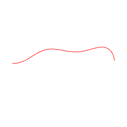
This is often referred as 'Bezier Spline'. With Cubic Hermite Spline, you can choose the points and the tangents of the curves that goes through control points.
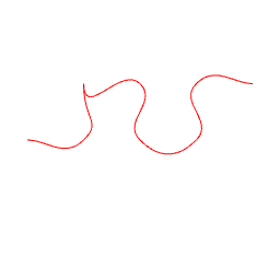
You can either define the tangents of your choice, as demonstrated for the 3rd point, or auto-generate them as Catmull-Rom spline, or even straight lines.
See Procedural::CubicHermiteSpline2 for a shape and Procedural::CubicHermiteSpline3 for a path.
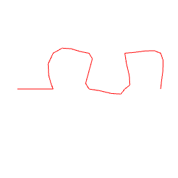
Catmull-Rom Spline
It's a particular case of Cubic Hermite Spline, in which tangents are automatically calculated. Note that its the equivalent of Ogre::SimpleSpline, and there's even a conversion function between the two.
See Procedural::CatmullRomSpline2 for a shape and Procedural::CatmullRomSpline3 for a path.
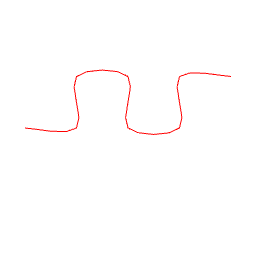
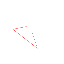
Kochanek Bartels Spline
Kochanek-Bartels spline is defined by control points and 3 parameters : tension, bias and continuity.
Here's a description of what they do :
| Parameter | +1 | -1 |
|---|---|---|
| Tension | Tight | Round |
| Bias | Post Shoot | Pre shoot |
| Continuity | Inverted corners | Box corners |
See Procedural::KochanekBartelsSpline2 for a shape.
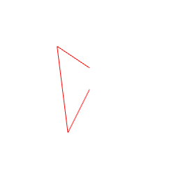
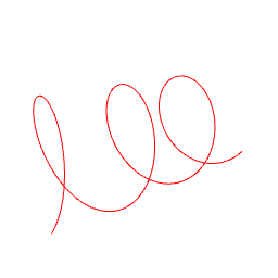
Rounded Corner Spline
This one consists in straight lines joining the control points, with corners replaced by circle arcs.
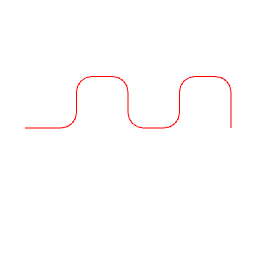
See Procedural::RoundedCornerSpline2 for a shape and Procedural::RoundedCornerSpline3 for a path.
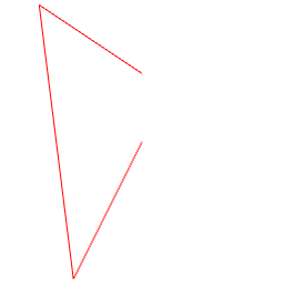
Bezier Curve
Splines and bezier curves are a few helper classes used to generate shapes or paths, by interpolating between a bunch of control points.
The bezier curve is not going through all control points.
See Procedural::BezierCurve2 for a shape and Procedural::BezierCurve3 for a path.
Track specifics
Tracks are used to represent a variable that varies along a path or a shape.
For that reason, the keys of the track are defined relatively to the points in the main curve.
There are 3 different addressing modes :
- AM_ABSOLUTE_LINEIC : the key represents a distance from the beginning of the curve.
- AM_RELATIVE_LINEIC : the key represents a relative distance inside the [0;1] segment, 0 being the beginning and 1 the end of the curve.
- AM_POINT : the key represents the index of a point in the main curve.
Shape specifics
Primitive transformations
You can do some standard transformations on you shapes.
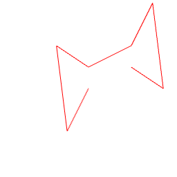
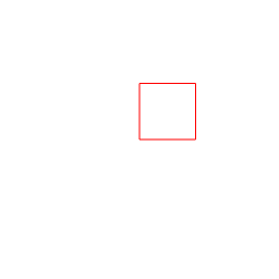
As an exemple, let's say we have this shape:
- Translation
- Scale
- Rotation
- Mirror
2D CSG
You can combine shapes together in order to produce new shapes, using boolean operations. Technically, the output is a multishape, because it doesn't always resolve to a single line.
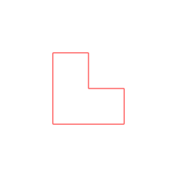
As an exemple, let's say we have these 2 shapes :
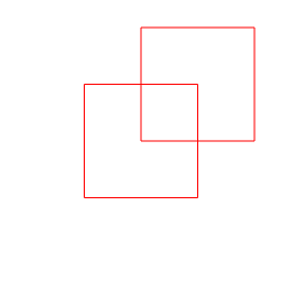
Supported boolean operations are :
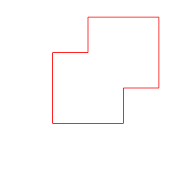
- Union : the result contains everything inside A plus evertyhing inside B
- Intersection : the result contains everything that is inside A and B
- Difference : the result contains everything that is in A but not in B
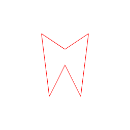
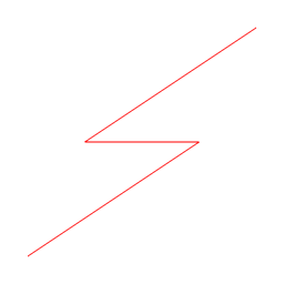
Thicken
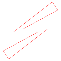
A "thin" shape can be made "thick" by using the thicken operation.
before
after
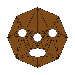
Triangulation
A constrained triangulation can be performed on a shape or a multishape. It means that points from the shape(s) are joined together to form triangles.
The algorithm used is Bowyer-Watson, which is an implementation of a Delaunay triangulation (Delaunay simply means that triangulation is 'best quality', ie has as few thin triangles as possible)
The main use of triangulation in OgreProcedural is just for extrusion tips, but you can use it for your own purposes.
Shape Primitives
There are a couple of pre-existing shape primitives. After creation it's possible to receive a Shape object by calling realizeShape()
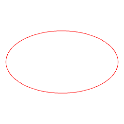
CircleShape

EllipseShape
RectangleShape
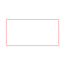
See Procedural::RectangleShape
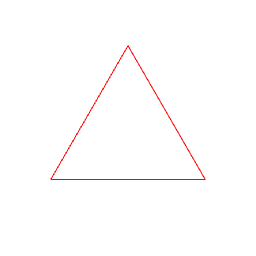
TriangleShape
MultiShapes
A MultiShape is a collection of normal shapes.
TextShape
Creates shapes from characters of a given text (FreeType required).
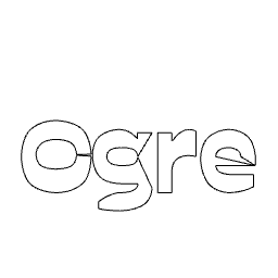
See Procedural::TextShape
Path primitives
At the moment there is only one path primitive. After creation it's possible to receive a Path object by calling realizePath().
HelixPath
SVG
It is really easy to import SVG files and extrude their shapes:
Example
The Sample_SVG project demonstrates how to load various shapes from a SVG file and extrude them.