|
OGRE-Next 4.0.0unstable
Object-Oriented Graphics Rendering Engine
|
|
OGRE-Next 4.0.0unstable
Object-Oriented Graphics Rendering Engine
|
The Compositor is a Core and key component in Ogre 2.0. In 1.x, it was just used for fancy post-processing effects. In 2.0, it's the way to tell Ogre how you want to render the scene. Without setting it up, Ogre won't render to screen.
With the Compositor, the user stops having to deal with setting Viewports, RenderTargets, updating these RenderTargets every frame, etc.
Instead the user has now to setup Nodes and a Workspace. The workspace is the top level system where the user indicates which Nodes he wants to use, how they will be connected, which global render textures will be declared (which can be seen by all nodes from the same workspace), where to render the final output (i.e. RenderWindow, an offscreen RenderTexture) and which SceneManager to use. The user can have multiple workspaces active at the same time.
The new Compositor system was heavily inspired by Blender's Compositor system. Picture from Blender:
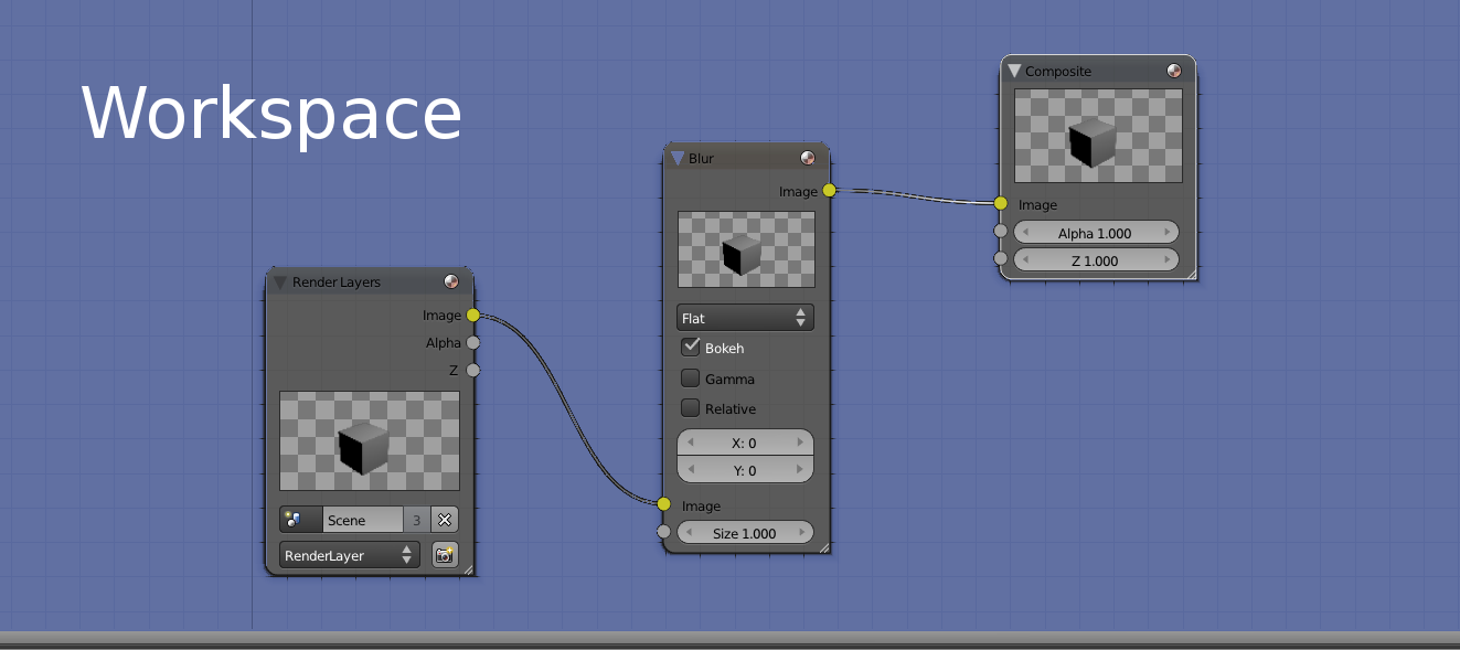
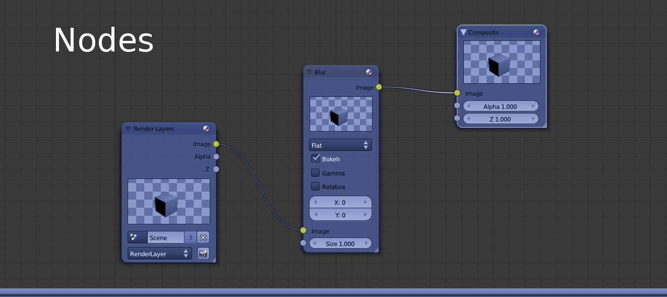
Compositor script syntax hasn't changed much, which should make porting them quite easy. Internally though, the new system was written from scratch (while reusing & reviewing some of the existing code); as the previous Compositor was stack-based, while the new one is node-based.
So, if you used to manipulate the Compositor directly from C++; porting efforts could be considerably bigger.
A compositor node most likely resembles what used to be "a compositor" in 1.x
The following node clears the RT and draws everything that is in the render queue #50
Where is Input_as_MyLocaName defined? What is its resolution? Its bit depth? The RT comes from the input channel, so the answer is that it depends on how the Workspace will connect this node. The Workspace may pass a local RTT declared in a previous node or it could pass RenderWindow.
A node's texture may come from three different sources:
The following script declares a local texture of resolution 800x600, clears it to violet, and puts it in the output channel #0 (so other compositor nodes can use it as input):
You may have noticed the syntax for declaring the RTT is similar as it was in Ogre 1.x
For more information on the syntax see texture.
Input channels are numbered. An input channel must be given a name so that they can be referenced locally at node scope by all target passes. There can't be any gaps (i.e. you can't use channels 0 & 2 but not 1).
Output channels are also numbered and must be assigned an RTT. This number will be later used by the Workspace to perform the connections.
The workspace will be responsible for connecting node A's output channels with node B's input channels. In other words, channels are a way to send, receive and share RTTs between nodes.
The only restriction is that global textures can't be used neither as input or output (global textures are referenced directly). There can be more input channels than output channels, viceversa, and there may be no input nor output channels (i.e. when working with global textures alone).
The following node definition (which does no rendering):
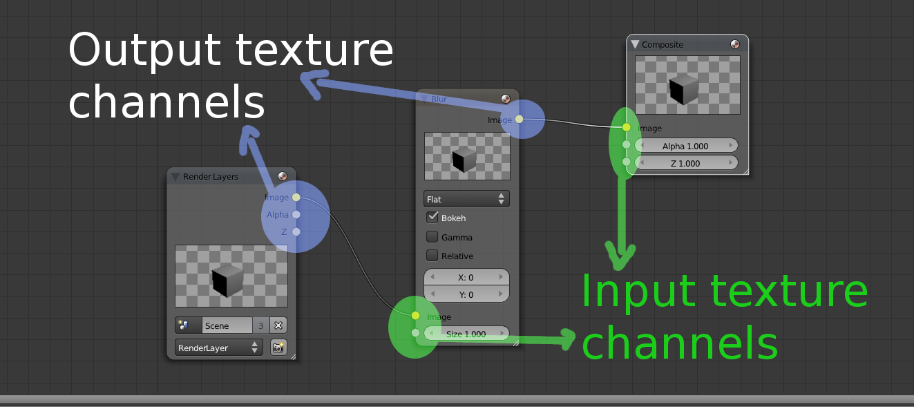
Drawing inspiration from Blender's compositor system, the little dots on the left would be the input channels, while the dots on right would be the output texture channels:
Global textures are declared at workspace scope and have the same syntax as local textures. There are a few restrictions:
global_ is illegal.Global textures are as powerful/dangerous as global variables are in C++. The main reason of their existence is that many nodes may use temporary rtts to perform their work, and it's very wasteful to declare these intermediate rtts on every node when they can be shared and reused.
Sharing and reusage can also be achieved through input & output channels, however for temporary rtts (or rtts that are accessed very frequently, i.e. a deferred shader's G Buffer) it would lead to connection hell; and hence global textures are a much better fit.
The input(s) to this node. This clause may be repeated. A node definition may have no inputs.
| channel_id | channel_id is a number in range [0; inf) but must be consecutive and continuous (no gaps, i.e. define channel 0, 2, but not 1). |
| local_texture_name | An arbitrary & unique name, cannot start with global_. |
The input(s) from this node. This clause may be repeated. A node definition may have no outputs.
| channel_id | channel_id is a number in range [0; inf) but must be consecutive and continuous (no gaps, i.e. define channel 0, 2, but not 1). |
| local_texture_name | An arbitrary & unique name, cannot start with global_. |
For UAV buffers. Same as with regular input textures, except you can reference global buffers, and global buffers don't have to start with global_.
If a local buffer and a global buffer have the same name, the local buffer takes precedence.
| channel_id | channel_id is a number in range [0; inf) but must be consecutive and continuous (no gaps, i.e. define channel 0, 2, but not 1). |
| local_texture_name | An arbitrary & unique name. |
For UAV buffers. Same as with regular output textures, except you can reference global buffers, and global buffers don't have to start with global_.
If a local buffer and a global buffer have the same name, the local buffer takes precedence.
For parameters, see in_buffer
Custom string that will be hashed to identify this Node definition. Useful for classifying nodes into categories.
Multiple nodes can have the same custom_id.
From C++ you can use:
When creating the Workspace instance, the C++ code will ask for the RT which should be the ultimate target (i.e. the RenderWindow). This RT is very important as keywords like target_width_scaled and settings like default msaa & pixel format will be based on the attributes from this main RT. This feature will be seen in more detail in the Workspace section.
node->connectFinalRT and supply a texture pointer (i.e. if the final RenderTarget is a RenderTexture) that can be bound. An automated way of doing this is not yet implemented.Targets include multiple passes. Their main purpose is define to which RenderTarget the passes will render to.
What's worth noting is that targets accept an optional parameter 'slice'.
The slice parameter is optional and refers to which slice or face from a 3D texture (or cubemap or 2D array) to use from the given texture. Valid values can be numeric or the hint '+X'. '-X', '+Y', '-Y', '+Z', and '-Z'.
Default value is no.
When yes, this setting is meant to be used with skip_load_store_semantics for optimization on mobile/TBDR targets, but should be used with care.
skip_load_store_semantics allows OgreNext to execute multiple consecutive passes as if they were only one.
An obstacle for this is that barriers from all theses passes must be issued before the first pass executes; otherwise the passes need to be internally broken up and OgreNext will complain if skip_load_store_semantics on but we can't merge the passes.
target_level_barrier yes means that an extra hidden pass will be inserted at the beginning of the target and issue all necessary barriers from subsequent passes:
Note that not always target_level_barrier yes can be successful.
For example if pass A needs texture X to be in state Texture for sampling but pass C needs that same texture in state Uav then we have a contradiction as we can't transition to two states at the same time.
The only solution is to break up the passes and issue two barriers. Note that you can however issue break ups manually:
Types of passes:
All passes share the following script parameters:
| type | must be one of the supported types: clear, quad, resolve, render_scene, stencil, custom, etc. |
| customId | Optional. It is used by custom passes to give the registered custom pass provider the means to identify multiple types, in case there are more than one type of custom passes. |
Number of times this pass will be executed. Default is -1, which means always execute.
When the execution count hits that value, it won't executed again until a d3d device reset, resize or workspace recreation (the execution count is reset and executed N times again)
This parameter replaces the only_initial parameter in Ogre 1.x.
Whether to flush the command buffer at the end of the pass.
This can incur in a performance overhead (see OpenGL's glFlush and D3D11' ID3D11DeviceContext::Flush) for info.
Usually you want to leave this off. However for VR applications that must meet VSync, profiling may show your workload benefits from submitting earlier so the GPU can start right away executing rendering commands.
The main reason to use this is in CPU-bound scenarios where the GPU starts too late after sitting idle.
An arbitrary user-defined numeric ID used for identifying individual passes in the C++ code.
From C++ you can access it via:
8-bit hex value. Specifies the execution mask. For more information see Stereo and Split-Screen Rendering for more information. Default is 0xFF except for clear passes, which default to 0x01.
8-bit hex value. Specifies the viewport modifier mask. For more information see [Stereo and Split-Screen Rendering for more Stereo and Split-Screen Rendering for more information. Default is 0xFF except for clear passes, which default to 0x00.
Disables colour writes. Useful for Z prepass passes; or pixel shaders that output to an UAV instead of a regular RenderTarget (like a Render Texture).
Default: on.
User defined text for identifying this pass by name in profilers and GPU debuggers such as RenderDoc.
Specifies the viewport. Supported by many other passes (e.g. render_quad, render_scene). The default is 0 0 1 1 which covers the entire screen. Values should be between 0 and 1.
When 4 parameters are suplied, the scissor box will match the viewport's. All 8 parameters allow to set a custom scissor box.
When the optional 'idx' parameter is supplied at the beginning there will be either 5 or 9 parameters instead of 4 or 8 respectively.
This index allows you to set multiple viewports for e.g. instanced_stereo or for shaders that make use of gl_ViewportIndex/SV_ViewportArrayIndex. When not provided, this value defaults to 0. The value is in range [0; 16)
The Compositor will automatically share Viewport pointers between different passes to the same RenderTarget (even for different nodes) as long as they share the exact same parameters.
Tells OgreNext that you plan on using texture_name for sampling during this pass.
Usually this can be inferred (e.g. render_quad's input parameter).
Reasons for using expose:
OgreNext must know which textures may or will be used during the pass so resource transitions and barriers can be issued in explicit APIs like DX12 and Vulkan (also OpenGL has rudimentary memory barriers that are needed if Compute Shaders are involved).
Without it, you may get exceptions when using the Vulkan RenderSystem, or Vulkan Validation Errors (when debug validation layers are active).
When yes, the load and store semantics will be ignored. Use with care as improper usage may lead to rendering bugs or crashes.
Normally OgreNext tries to merge passes when possible but certain advanced uses are impossible or difficult to get automatically merged, thus this flag indicates we want.
e.g.
The reason you should be careful is that we assume you know where you're drawing. Consider the following example:
This script will not behave as expected because both render_quad passes will draw to TargetA!
This is because with skip_load_store_semantics you're telling Ogre not to set UnrelatedTargetB as the current target because OgreNext should assume it already is the current target.
Likewise there should be no barriers to execute because barriers force the pass to 'close' which means store semantics must be executed; and to open another pass we must execute load semantics again (see target_level_barrier to solve this problem).
We try to perform validation checks in Debug mode to avoid these type of errors, but we can't cover them all.
This setting is an optimization specifically aimed at mobile and you should pay attention to errors, the Ogre.log, Vulkan Validation Layers, and tools like RenderDoc to be sure rendering is happening as intended.
This is often referred as "Load Actions". To understand their relevancy please read Load Store semantics.
Sets all RTV parameters (all colour targets in MRT + depth + stencil) to the same load action.
| dont_care | Assume uninitialized values are present and will be completely overwritten. This is discouraged on depth & stencil buffers because it precludes optimizations (e.g. Hi-Z, Early Z, Depth Compression, etc.). See LoadAction::DontCare. |
| clear | Clear the whole texture to the set clear_colour/clear_depth/clear_stencil values. See LoadAction::Clear. |
| clear_on_tilers | See LoadAction::ClearOnTilers. |
| load | Load the contents that were stored in the texture. See LoadAction::Load. |
Sets the load action for each and/or all the colour textures. Does nothing if there are no colour textures.
| N | Value in range [0; num_mrt) to reference the colour target in an MRT. For non-MRT RTVs, use 0 or skip this parameter. |
| dont_care|clear|clear_on_tilers|load | See Load Actions in all. |
Sets the load action for the Depth Buffer. Does nothing if there is no depth buffer.
| dont_care|etc | See Load Actions in all. |
Sets the load action for the Stencil Buffer. Does nothing if there is no stencil buffer.
| dont_care|etc | See Load Actions in all. |
Sets the colour to set the texture to. The kayword colour_value is the same, and retained due to old naming conventions.
| N | Value in range [0; num_mrt) to reference the colour target in an MRT. When absent, it sets all colour targets in the MRT to the same value. |
| rgba | Four float values to set the colour target to. e.g. clear_colour 0.2 0.4 0.5 1.0. |
Sets the colour texture to either the clear_colour or White - clear_colour depending on whether OgreNext is configured to use reverse depth. See Ogre::RenderSystem::isReverseDepth.
This setting is useful when storing depth data into colour textures such as PFG_R32_FLOAT.
| N | Value in range [0; num_mrt) to reference the colour target in an MRT. When absent, it sets all colour targets in the MRT to the same value. |
| rgba | Four float values to set the colour target to. e.g. 0.2 0.4 0.5 1.0. When using reverse Z, the final colour value will be 0.8 0.6 0.5 0.0. |
Sets the value to set the depth buffer to.
| value | Floating point value to set the depth to. Usually in range [0; 1], but not necessarily (depends on API support). |
Sets the value to set the stencil buffer to.
| value | Integer value to set the depth to. Usually in range [0; 255] since to date all known stencil formats are 8-bit. |
See Ogre::CompositorPassDef::mWarnIfRtvWasFlushed
Default: False.
This is often referred as "Store Actions". To understand their relevancy please read Load Store semantics.
Sets all RTV parameters (all colour targets in MRT + depth + stencil) to the same store action.
| dont_care | Discard, leaving the texture contents in an undefined state. You should not attempt to read from it after this. See StoreAction::DontCare. |
| store | Do not resolve. Useful if you have to interrupt rendering to a RenderTarget, switch to another RenderTarget, and come back to continue rendering; asuming you didn't need to sample from this texture (to fetch what has been rendered so far). See StoreAction::Store. |
| resolve | Always resolve the texture once we're done rendering, and we do not care about the contents of the MSAA surface. This flag won't work on non-MSAA textures and will raise an exception. You should not continue rendering to this texture after this, unless you clear it. See StoreAction::MultisampleResolve. |
| store_and_resolve | Always resolve the texture once we're done rendering, and we do care about the contents of the MSAA surface. It is valid to use this flag without an MSAA texture. This flag is mostly meant for explicit-resolve textures as Ogre users have no way of accessing MSAA contents. However it may be useful if you need to interrupt rendering to a RenderTarget, switch to another RenderTarget while also sampling what has been rendered so far, and then come back to continue rendering to MSAA. See StoreAction::StoreAndMultisampleResolve. |
| store_or_resolve | This is the compositor's default. It behaves like 'Store' if the texture is not MSAA. It behaves like 'MultisampleResolve' if the texture is MSAA. See StoreAction::StoreOrResolve. This is the default value. |
| N | Value in range [0; num_mrt) to reference the colour target in an MRT. For non-MRT RTVs, use 0 or skip this parameter. |
| dont_care|etc | See Store Actions in all. |
Sets the store action for the Depth Buffer.
| dont_care|etc | See Store Actions in all. |
Sets the store action for the Stencil Buffer.
| dont_care|etc | See store Actions in all. |
When true, this pass must only execute if the current GPU is not a TBDR GPU. When false, this pass always executes. Default: false.
This setting is tightly related to Load Action clear_on_tilers.
Tells the pass which buffers to clear.
| colour | Tells the pass to clear all colour target Does nothing if there is no colour buffer(s). |
| depth | Tells the pass to clear the depth buffer. Does nothing if there is no depth buffer. |
| stencil | Tells the pass to clear the stencil buffer. Does nothing if there is no stencil buffer. |
generate_mipmaps doesn't have special parameters other than the shared ones that are still relevant (i.e. identifier). They're useful for explicitly populating the lower mip levels after you've done rendering.
Default is api_default which will ask the API or driver to generate them for you. If the API does not support it (e.g. DX12) then Compute will be used.
| api_default | Uses whatever the API provides. Which is usually a bilinear downscale. |
| compute | At the moment, it is the same as compute_hq. |
| compute_hq | Uses a high quality gaussian filter. Useful for fast & high quality mipmap generation. Uses a compute shader. |
Integer value. Default is 8. Must be positive, even number. Defines the kernel radius of the compute_hq gaussian filter.
The standard deviation of the compute_hq gaussian filter. The default is 0.5.
Quad passes have the same syntax as 1.x; plus the following keywords have been added:
Default is no. When no; the compositor will draw a fullscreen triangle. Due to how modern GPUs work, using two rectangles wastes GPU processing power in the diagonal borders because pixels are processed at least in 2x2 blocks; and the results from the pixels out of the triangle have to be discarded. A single triangle is more efficient as all blocks are fill the viewport area, and when the rectangle goes out of the viewport, the gpu efficiently clips it.
When the viewport is not 0 0 1 1; this value is forced to yes. The following picture illustrates a fullscreen triangle:
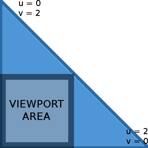
Interpolation will cause that the effective UV coordinates will be in the [0; 1] range while inside the viewport area.
Using camera_far_corners_world_space will also force to use a quad instead of a tri (but camera_far_corners_view_space works with tris)
For an explanation of why this is a performance optimization, refer to Optimizing the basic rasterizer by Fabien Giesen.
Name of the low level material to use.
Name of the Hlms datablock to use.
Texture to bind to the material or datablock.
| N | Material's Texture Unit to set. |
| texture_name | Name of the texture. Must be a local, input or global texture. |
Sends to the vertex shaderthe camera's frustum corners in either world space or view space through the NORMALS semantic.
This is particularly useful for efficiently reconstructing position using only the depth and the corners (see Samples/2.0/Tutorials/Tutorial_ReconstructPosFromDepth).
| camera_far_corners_view_space | Sends camera frustum corners in view space. |
| camera_far_corners_view_space_normalized | Sends camera frustum corners in view space. See Ogre::CompositorPassQuadDef::VIEW_SPACE_CORNERS_NORMALIZED. Note: It divides the whole vector by the far plane; causing dir.z to be always -1 (but the vector itself isn't unit-length). |
| camera_far_corners_view_space_normalized_lh | Same as camera_far_corners_view_space_normalized but left-handed. Note: dir.z is always 1. |
| camera_far_corners_world_space | Sends camera frustum corners in world space. |
| camera_far_corners_world_space_centered | Sends camera frustum corners direction, but it is centered around origin (0, 0, 0). |
| camera_direction | Same as camera_far_corners_world_space_centered but normalized (values are in range [0;1]) which is useful for sky rendering & atmospheric scattering. See TutorialSky_Postprocess sample. |
Interesting read: Reconstructing Position From Depth Part I, Part II, Part III
Sets the current camera to use if you want to use a different one from the default one.
Rotates the camera 90°, -90° or 180° depending on the value of the slice index. See Ogre::CompositorPassQuadDef::mCameraCubemapReorient.
This is the main pass to render most of the scene.
Sets the first render queue ID to start rendering from. The default is 0. Must be a value in range [0 and 255].
The value is inclusive (Objects in ID = rq_first get rendered).
The default is max which is a special parameter that implies the last active render queue ID. If numeric, value must be between 0 and 255.
The value is not inclusive (Objects in ID = rq_last do not get rendered).
Applies a bias multiplier to the lod. Valid values are in range [0; Inf).
A higher lod bias causes LODs to pop up sooner and should be preferred on slower devices.
Default: 1.0
When no, the LOD list won't be updated, and will use the LOD lists of calculated by a previous pass. This saves valuable CPU time.
Useful for multiple passes using the same lod_camera (without a pass in the middle with a different lod_camera that would override the cached LOD lists).
If your application is extremely CPU bound, and hence you don't need LOD, turning this setting to false in all passes will effectively turn lodding off (and alleviate the CPU).
Default: yes; except for passes belonging to shadow nodes, which is forced to false unless lod_camera is a non-empty string.
See Ogre::CompositorPassSceneDef::mUpdateLodLists.
When true, the frustum culling is skipped in this pass. Data from the previous frustum culling execution is used instead.
This is useful if you execute two render_scene passes in a row that are almost identical (e.g. early depth pre-pass followed by a normal render); thus saving lots of valuable CPU time.
Visibility mask to be used by the pass' viewport. Those entities that fail the test 'entityMask & visibility_mask' will not be rendered.
There are no significant changes to Ogre 1.x, except that the script compiler now accepts hexadecimal values with the 0x prefix instead of decimal values.
Visibility mask to be used by the pass for culling lights in Forward+.
Those entities that fail the test 'entityMask & light_visibility_mask' will not be used as non-shadow-casting lights during this pass.
This will give you a relatively efficient way to control with coarse granularity which lights affect which objects.
Note that this uses the mask set via light->setVisibilityMask, not the one set via light->setLightMask.
Specifies the shadow node to use for rendering with shadow maps. See section about *Shadow Nodes* for more information. When a shadow node's name is provided, the second parameter defaults to first.
Off by default.
| off | Set to off if it should not use shadows. |
| shadow_node_name | The name of the shadow node to use. Mutually exclusive with off. |
| first | Optional. Default. Automatically calculates whether we should reuse or recalculate, based on whether this is the first node. Mutually exclusive with reuse & recalculate. |
| reuse | Optional. Reuses existing rendered shadow map data, regardless of whether it's valid or if OgreNext believes it should be redrawn. Mutually exclusive with first & recalculate. |
| recalculate | Optional. Forces to redraw the shadow map, even if OgreNext believes it should not. This is useful if you've modified the scene via listeners or rendering in a complex way that OgreNext has no way to know the shadow node should be redrawn. Mutually exclusive with first & reuse. |
Whether to render Overlays from the OverlaySystem component. On by default for regular nodes, Off by default on shadow nodes. The goal is that eventually Overlays obey RenderQueue IDs like everything else, but it was too hard to port (Overlay system is tad bit complex...) so this hack/flag was created. It will be eventually removed.
See Overlays for more info.
When not specified, the default camera is used for rendering the pass (this default camera is specified when instantiating the workspace from C++).
When a name is given, the Compositor will look for this camera and use it. Very useful for reflection passes (mirrors, water) where the user wants to be in control of the camera, while the Compositor is associated with it. The Camera must be created by the user before the workspace is instantiated and remain valid until the workspace is destroyed.
The camera point of view from which the LOD calculations will be based from (i.e. useful for shadow mapping, which needs the LOD to match that of the user camera). When an empty string is provided, OgreNext will assume the lod camera is the same as the current camera, except for shadow nodes in which it will assume it's the lod_camera from the normal pass the shadow node is attached to. Default: Empty string.
In VR we want to reuse the same cull list for both eyes. Additionally we'd like to calculate shadows for both eyes once, rather than once per eye. This setting allows setting a cull camera different from the rendering camera that should be placed in such a way that the cull camera's frustum encompases both left and right eye. When this string is empty, the regular camera is used. Default: Empty string.
When Yes, the camera will be reoriented for rendering cubemaps, depending on which slice of the render target we're rendering to (3D, Cubemaps and 2D-array textures only). Its original orientation is restored after the pass finishes. The rotations are relative to its original orientation, which can produce counter-intuitive results if the Camera wasn't set to identity (unless that's the desired effect). See Target section on how to indicate which slice should we render to. Default: No.
Note: if the target is not a cubemap, Ogre will still try to rotate the camera, often to unintended angles.
When yes, this pass will use Forward3D/ForwardClustered (must be enabled first by the developer via C++, see Forward3D sample). When No, Forward3D will not be used for this pass, which can improve performance both CPU and GPU side (but many lights are likely not going to be drawn or used).
Default: Yes.
Details: CPU side, lights won't be culled against the camera (only a saving if F3D didn't already have a cache from a previous pass during the same frame, with the exact same camera and angle). GPU side, the pixel shaders will be lighter.
Very similar to flush_command_buffers. Does not do anything if 'shadows' is set to 'reuse' (or was set to 'first' and this node is not the first).
See Ogre::CompositorPassSceneDef::mFlushCommandBuffersAfterShadowNode.
Indicates this is a prepass render. HlmsPbs implementation will render a GBuffer with normals and shadow mapping information. See ScreenSpaceReflections sample for an example on how to use it.
Indicates this pass will take advantage of the data generated during the prepass, which means depth buffer writes may be forced to off; normals will be sourced for the GBuffer. And if present, a reflection texture will be used for calculating SSR (Screen Space Reflections).
See Ogre::CompositorPassSceneDef::mGenNormalsGBuf.
Tells the HlmsPbs implementation the necessary data to perform refractions.
See sample Samples/2.0/ApiUsage/Refractions on how to set it up.
| depth_texture | Name of the depth texture used for rendering the scene without refractive objects. |
| refractions_texture | Name of the colour texture used for rendering the scene without refractive objects. |
read_only.read_only, which means the current render_scene cannot write to the depth or the stencil buffers.Value in range [0; 254]. When set to 255, it is disabled.
See Samples/2.0/Tutorials/Tutorial_TextureBaking See Ogre::CompositorPassSceneDef::mUvBakingSet.
Float value in for offsetting U & V values, in pixels.
See Samples/2.0/Tutorials/Tutorial_TextureBaking See Ogre::CompositorPassSceneDef::mUvBakingOffset.
See Samples/2.0/Tutorials/Tutorial_TextureBaking See Ogre::CompositorPassSceneDef::mBakeLightingOnly.
Whether to use instanced stereo, for VR rendering. See InstancedStereo and OpenVR samples. You will probably want to also set multiple viewports, at the very least viewports 0 and 1
This pass enables force-updating multiple shadow nodes in batch in its own pass
This is useful because shadow nodes may "break" a render pass in 3:
This is an unnecessary performance hit on mobile (TBDR) thus executing them earlier allows for a smooth:
Don't forget to set shadow nodes to reuse in the pass scene passes or else you may overwrite them unnecessarily
Usage is simple:
Stencil passes are little more flexible than in Ogre 1.x; always remember to restore the stencil passes before leaving the node otherwise next nodes that will be executed may use unexpected stencil settings.
Most relevant changes are that two sided stencil can now be definted with more flexibility (it's not a boolean anymore), and that syntax has slightly changed to accomodate for this change:
The read mask is new, and now the fail_op, depth_fail_op & pass_op must be enclosed between brackets.
Valid values are 'both' 'front' and 'back'. 'both' is just a shortcut for defining front and back at the same time with less typing.
This is a new feature introduced in Ogre 2.1. s stands for Unordered Access Views, in D3D's jargon. OpenGL users know UAVs as the feature combination of image textures (imageLoad, imageStore) and SSBOs (Shader Storage Buffer Object). UAVs are powerful beasts because they allow random read and write access from a shader, and even support atomic operations. Proper use of them can achieve incredible results that couldn't be done without UAVs, but improper use can severely hurt performance.
There's quite a discrepancy between D3D11 & OpenGL in how they treat UAVs from API interface perspective. D3D11 equals UAVs to RenderTargets; while OpenGL equals them more like textures.
In fact, the D3D11 API call to bind UAVs must set RenderTargets at the same time. There is no API call to only set UAVs. To make things harder, D3D11 forces UAVs to share slots with RenderTargets; and there are up to 8 slots in total (64 when using D3D11.1 on Windows 8.1). Which means if you're using an MRT with 3 targets, you only have 5 slots left for UAVs.
We can guess for performance improvements: this way D3D11 can check for hazards when setting RTs and UAVs (i.e. make sure you don't bind the same resource as both RT and UAV) while they still use the same hazard checking they do for textures to check that you're not binding a texture at the same time it is bound as an RT/UAV.
If the UAV equals a texture, as in OpenGL; they would have to check textures against textures every time a texture changes, which is O( N! ) complexity; and also a very common operation. Considering past experiences, we're guessing OpenGL just simply skips the check and lets the hazard happen (which is cool when there are hardware extensions that allow you to read/write from these resources at the same time as long as you abide to certain rules).
Because D3D11 is more restrictive than OpenGL, our interface resemble's D3D11.
Offset for all UAV slots. For example if you bind an uav to slot 3 and the starting slot is 2; the uav will actually be bound to uav slot 5. When set to 255, the slot offset is ignore and leaves the last setting made.
Default: 255 (by default Ogre sets it to 1).
Sets a texture visible in the current compositor scope (i.e. global textures, input textures, local textures).
| slot | 0-based index to bind to. |
| texture_name | Name of the texture. Must be global, input or local texture. |
| read | If present, it states you want to read from this UAV in the next vertex/pixel shaders. If absent, you don't intend to read. |
| write | If present, it states you want to write into this UAV in the next vertex/pixel shaders. If absent, you don't intend to write. |
| pixel_format | Optional. The pixel format to bind as. If absent, it uses the original pixel format. Note: the texture must have been declared with reinterpretable if reinterpreting as a different pixel format. |
| mipmap | The mipmap value must be following by a number (0-based). If not present, default value is 0. |
| Flag Combination | Status |
|---|---|
| read | valid |
| Read + write | valid |
| write | valid |
| <nothing> | invalid |
Example:
Will bind the global texture 'global_myTexture' to slot 3, will have both read & write access, and use mipmap level 5.
If only the slot is specified, the slot will be cleared.
Exactly the same as uav. But instead of sourcing the texture by name from the Compositor scope, the name is referencing a texture that can be accessed via TextureGpuManager::findTextureNoThrow.
Sets an UAV buffer visible in the current compositor scope (i.e. global buffers, input buffers, local buffers).
| slot | Same as uav |
| read | Same as uav |
| write | Same as uav |
| offset_bytes | Default: 0. Optional. Offset in bytes to bind. |
| size_bytes | Default: 0. Optional. Size in bytes to bind. When size_bytes = 0, we assume you want to bind from the offset until the end of the buffer. |
Note there may be HW alignment restriction on which offset you specify. Multiples of 256 bytes are a safe bet.
Note that uav_buffer slots are shared with uav texture's. Binding both to the same slot index will only result in one of them being available.
If only the slot is specified, the slot will be cleared.
When false, all previous UAVs in all slot will be cleared. When true, only the UAV slots modified by this pass will be affected. Default: true.
Compute passes let you run a compute job. It can read textures, read/write to UAV textures, and read/write to UAV buffers.
Sets the name of the compute job to run (an HlmsComputeJob).
See uav_queue description. The presence of allow_write_after_write means the compositor will not insert a barrier between to consecutive passes that writes to the UAV without reading.
See uav_queue description. The presence of allow_write_after_write means the compositor will not insert a barrier between to consecutive passes that writes to the UAV without reading.
Binds a texture to the texture unit. Syntax is the same as render_quad's input. The slot is not shared with the uav's.
Compute passes don't really belong to a render target. However due to the Compositor's design, they must be specified within a render target. You may do so within a valid render target:
Or to a null dummy render target, which occupies almost no memory:
This pass lets you perform a raw copy between textures. You can think of it as a literal mempcy.
This pass does not require a named target and thus can be left blank, e.g.
The name of the texture to copy.
The name of the texture that will hold the copy.
Sets which mipmaps to copy. Mipmaps to copy are in range [first_mip; first_mip + num_mipmaps).
If num_mipmaps is the special value 0, then all mipmaps starting from first_mip until the end are copied.
| name |
A locally unique name must be assigned (and cannot start with global_ prefix).
| width | |
| height | The dimensions of the render texture. You can either specify a fixed width and height, or you can request that the texture is based on the physical dimensions of the viewport to which the compositor is attached. The options for the latter are either of
|
| depth |
Used by 2d_array and 3d textures. Specifies their depth / number of slices. It's automatically forced to 1 for 2d textures and 6 for cubemaps.
| pixel_format |
The pixel format of the render texture. This affects how much memory it will take, what colour channels will be available, and what precision you will have within those channels. Most common options are PFG_RGBA8_UNORM_SRGB, PFG_RGBA8_UNORM, PFG_RGBA16_FLOAT, PFG_R16_FLOAT, PFG_RGBA16_FLOAT, PFG_R32_FLOAT. See Ogre::PixelFormatGpu for all options.
| msaa |
Explicitly specifies the MSAA count. Valid values are: 1, 2, 4, 8, 16.
Note that this is subject to GPU support (e.g. some mobile GPUs don't support MSAA 2x and most consumer desktop GPUs don't support values > 8).
| msaa_auto |
Uses the same MSAA setting as the global setting for the workspace.
| depth_pool |
When present, this directive has to be followed by an integer. This one sets from which Depth buffer pool the depth buffer will be chosen from. All RTs from all compositors with the same pool ID share the same depth buffers as long as it's possible (must have the same resolution, must have the same depth_texture setting). RenderWindows can**not** share their depth buffers due to API limitations on some RenderSystems. When the pool ID is 0, no depth buffer is used. This can be helpful for passes that don’t require a Depth buffer at all, potentially saving performance and memory. Default value is 1.
| depth_texture |
When present, the RTT indicates you want to later access the depth buffer's contents as a texture in a shader. This feature is discouraged starting OgreNext >= 2.2 because using RTVs gives you better control.
| uav |
When present, the texture can be used as an UAV (also called "STORAGE" in Vulkan lingo).
| 2d_array|3d|cubemap |
When present, the texture will be created as a 2d_array, 3d or cubemap. Mostly relevant for UAVs but is also useful for rendering. See Target slice parameter.
| mipmaps |
Default: 1; Indicates how many mipmaps to use. 1 for none. Use 0 to fill all mipmaps until 1x1
| no_automipmaps |
When absent (default) and mipmaps are != 1, OgreNext will assume you may eventually use generate_mipmaps (not the Compute version) on this texture or call Ogre::TextureGpu::_autogenerateMipmaps from C++.
When present, it is not valid to use generate_mipmaps on this texture (except for the Compute version).
| reinterpretable |
When present, it indicates the texture may be reinterpreted to a different pixel format. e.g. PFG_RGBA8_UNORM as PFG_RGBA8_UNORM_SRGB, PFG_RGBA8_UNORM as PFG_R32_UINT, etc.
Not all formats can be reinterpreted into any format. The bpp must be the same. Compressed blocks (e.g. BCn) have specific rules. The reinterpretation must be supported by the GPU and API.
| explicit_resolve |
When absent (default), MSAA textures will have an extra non-MSAA copy where the contents are always resolved (unless store actions are not set to resolve).
When present, there is no extra copy; and you must setup the RTV manually with a different non-MSAA texture where to resolve to. See MSAA with Explicit Resolves.
| not_texture |
When absent (default), the texture can be bound as a regular texture for sampling (e.g. with point/bilinear filtering). When present, you can't sample from this texture. This flag is useful if you intend to use it together with uav or explicit_resolve.
Not long ago, MSAA support was automatic, and worked flawlessly with forward renderers and no postprocessing. Direct3D 9 and OpenGL were not able to access the individual MSAA subsamples from shaders at all.
Fast forward to the present, MSAA resolving should be performed after HDR to avoid halos around edges, and deferred shading can't resolve the G-Buffer otherwise aliasing only gets worse.
Direct3D10 and GL 3.2 introduced the ability of access the MSAA subsamples from within a shader, also giving the ability to write custom resolves.
For those unaware what "resolving MSAA" means; a very brief explanation is that when rendering using 4xMSAA, we're actually rendering to a RT that is twice the resolution.
"Resolving" is the act of scaling down the resolution into the real RT (i.e. think of Photoshop or Gimp's downscale filter modes). See the Resources section at the end for links to detailed explanations of how MSAA works.
To cleanly deal with this new feature without breaking compatibility with D3D9 & older GL render systems while at the same time being able to effortlessly switch MSAA on and off; the notion of "Explicit" and "Implicit" resolves were added.
By default all RTTs are implicitly resolved. The behavior of implicitly resolved textures mimics Ogre 1.x (except for implementation and design issues in Ogre 1.x that could cause an RTT to resolve multiple times per frame unnecessarily).
When you render and store actions are set to store_or_resolve, we will automatically resolve to the internal texture.
To perform explicit resolves you need to setup an RTV, see Advanced MSAA
Since Ogre 2.1; depth textures are supported. It has been a feature missing from Ogre since a long time by now.
Depth textures are a bit particular because they may not "own" the depth buffer. They're just a null render target with a "view" on an already existing depth buffer. But... what does this mean?
Depth Buffers can be tricky. Suppose the following example:
Which simply does "Render a depth only pass to myDepthTexture; and read the depth buffer contents with a render quad, and store the results in a coloured RTT called 'finalSSAO' ".
That one was easy. But what about this one?
The first pass is a pass that includes both colour and depth. The second one, we want to just take the depth and colour buffers separately as input textures to the SSAO material pass.
But how do we take the depth buffer? For that, we need to do two steps:
The solution is the following:
The only way to have shadows in Ogre is through shadow nodes.
Stencil shadows and "textured shadows" have been removed from Ogre 2.0; only depth shadow maps are supported.
A shadow node is a special type of Node (in fact, the class inherits from CompositorNode) that is executed inside a regular node (normally, a render_scene pass) instead of being connected to other nodes.
It is possible however, to connect the output from a Shadow Node to a regular Node for further postprocessing (i.e. reflective shadow maps for real time Global Illumination), but Shadow Nodes cannot have input. This particular feature (output to regular nodes) is still a work in progress at the time of writing since ensuring the regular node is executed after the shadow node has been executed can be a bit tricky.
Shadow nodes work very similar to regular nodes. Perhaps their most noticeable difference is how are RTTs defined. The following keywords are supposed at shadow node scope:
Specifies which shadow technique to use for the subsequent shadow map declarations. The default is uniform.
Only used by PSSM techniques. Specifies the number of splits per light. Can vary per shadow map. The number of splits must be greater than 2. Default is 3.
PSSM tends to be very unstable to camera rotation changes. Just rotate the camera around without changing its position and the shadow mapping artifacts keep flickering.
Ogre::PSSMShadowCameraSetup::setNumStableSplits allows you to fix that problem by switching to ConcentricShadowCamera for the first N splits you specify while the remaining splits will use FocusedShadowCameraSetup.
We achieve rotation stability by sacrificing overall quality. Using ConcentricShadowCamera on higher splits means exponentially sacrificing a lot more quality (and even performance); thus the recommended values are num_stable_splits = 1 or num_stable_splits = 2.
The default is num_stable_splits = 0 which disables the feature.
Normal-offset bias is per cascade / shadow map to fight shadow acne and self shadowing artifacts. Very large values can cause misalignments between the objects and their shadows (if they're touching).
Default is 168.0.
Constant bias is normally per material (tweak HlmsDatablock::mShadowConstantBias). This value lets you multiply it 'mShadowConstantBias * constantBiasScale' per cascade / shadow map
Large values cause peter-panning.
Default is 1.0.
Used only by PSSM techniques. Value should be in range [0; 1]. The default is 0.95. PSSM's lambda is a weight value for a linear interpolation between exponential and linear separation between each split. A higher lambda will use exponential distribution, thus closer shadows will improve quality. A lower lambda will use a linear distribution, pushing the splits further, improving the quality of shadows in the distance.
| Lambda | Close Shadows | Far Shadows |
|---|---|---|
| 0.0 | Low Quality | High Quality |
| 1.0 | High Quality | Low Quality |
Used only by PSSM techniques. Value in range [0; 1]. The default is 0.125; use 0 to disable it. PSSM's blend defines, in the closest N-1 splits, the blend band size. E.g., a value of 0.1 means that the farthest 10% of the first split is blended with the second split (and so on for the other splits). A higher blend reduces visible seams between splits at a cost of a slightly less defined shadow. See [Blend between Cascades] (https://msdn.microsoft.com/en-us/library/windows/desktop/ee416307(v=vs.85).aspx) for additional info.
Used only by PSSM techniques. Value in range [0; 1]. The default is 0.313; use 0 to disable it. PSSM's fade defines how much of the last split will fade out. E.g., a value of 0.1 means that the farthest 10% of the last split will fade out. A higher fade makes the transition from shadowed to non shadowed areas (and viceversa) smoother at a cost of a less visible distant shadow.
| number | The number of the shadow map being defined. |
| texture_name | What texture to use which must have already been declared, where the shadow map contents will be stored. |
| uv | Optional. After this keyword, 4 more numbers must follow (left, top, width, height). An atlas allows you to use a region of a texture. Instead of using the whole atlas content, you can use a region of it. This allows you to have multiple shadow maps in the same texture. |
| left | |
| top | Specifies the left & top origin of the shadow map inside the atlas. In UV space. in range [0; 1]. |
| width | |
| height | Specifies the width & height of the shadow map inside the atlas. In UV space. in range [0; 1]. |
| light | After light must follow the number for the light. Indicates which light index will be associated with this shadow map. This is useful for PSSM because multiple shadow maps may refer to the same light. |
| split | Optional. After split must follow the split index. Used by PSSM, indicates which split does this shadow map handle. |
Declaring a shadow map is not enough. You need to tell OgreNext what do you want to render to it and how. And for that you need render_scene passes.
Shadow nodes can be written with the regular target { pass render_scene {} } syntax. However when you have 6 shadow maps with the same exact pass settings, it's cumbersome to write the pass six times. Instead the shadow_map keyword repeats the passes for you.
The following is a basic script that will set a single shadow map with a focused setup:
The typical setup is to have one directional light for the sun. And then multiple point or spot lights.
This means directional light should use a PSSM setting for best quality while point & spot lights shadow maps could use focused or uniform.
The following script creates 3 shadow maps for 3 PSSM splits, and 3 additional ones for the remaining lights (which can be either directional or spot):
Instead of rendering each PSSM split into a different texture, you can use an atlas:
Point light shadow mapping must exploit the powerful compositor scripting capabilities: OgreNext uses DPSM (Dual Paraboloid Shadow Maps).
Please note we will be rendering to cubemaps, then converting to DPSM.
We won't be rendering directly as DPSM because testing shows it deforms too much when tessellation is low. We could support it, but it's not a priority. Thus OgreNext first needs to render to a cubemap, which can be shared by all shadow maps, and then a converter transforms it to DPSM.
The reason to use scene -> Cubemap -> DPSM is so that we keep a reasonable memory footprint and be atlas-friendly. If we use cubemaps directly and want to support 8 point lights at 1024x1024, then we would need 1024x1024x6x8 = 192MB.
However with DPSM it would be 8 DPSM and 1 cubemap: 1024x1024x4x8 + 1024x1024x4x6 = 56MB.
The following example setups a script to support two point lights (and only two point lights):
See Samples/Media/2.0/scripts/Compositors/ShadowMapDebugging.compositor for an example of a full script that can support directional, spot & point lights all in one, in a single atlas.
Each PASS_SCENE from regular nodes have three settings:
SHADOW_NODE_REUSESHADOW_NODE_RECALCULATESHADOW_NODE_FIRST_ONLYThis affect when shadow nodes are executed and how they cache their results. The default value is SHADOW_NODE_FIRST_ONLY; in which means Ogre should manage this automatically; however there are times when SHADOW_NODE_REUSE could be useful.
It's easier to explain what they do with examples.
Suppose the user has two render_scene passes, both have the same shadow node associated:
If using SHADOW_NODE_FIRST_ONLY, when the first pass is executed (opaque geometry), Ogre will first execute the shadow nodes, updating the shadow maps; then render the opaque geometry.
When the second pass is executed (transparent geometry), the shadow node won't be executed as the shadow maps are supposed to be up to date; hence the transparent geometry will reuse the results.
Another example: Suppose the user has three passes:
If using SHADOW_NODE_FIRST_ONLY; the shadow node will be executed before the opaque geometry pass.
Then the reflections' pass comes. It uses a different camera, which means there could be a different set of lights that will be used for shadow casting (since some techniques set shadow cameras relative to the rendering camera for optimum quality, pssm splits become obsolete, some lights are closer to this camera than they were to the player's camera, etc). Ogre has no choice but to recalculate and execute the shadow node again, updating the shadow maps.
When the third pass kicks in, the camera has changed again; thus we need to execute the shadow node... again!
Ogre will log a warning when it detects a suboptimal compositor setup such as this one. To be more specific, Ogre detects that the 3rd pass uses the same results as the 1st pass, but the shadow node is being forced to recalculate in the third one, instead of reusing.
There are several ways to solve this problem:
The setting SHADOW_NODE_RECALCULATE forces Ogre to always recalculate. Ogre will not issue a warning if it detects your node setup is suboptimal because of passes using SHADOW_NODE_RECALCULATE.
Forcing recalculation only makes sense when the application makes relevant changes to the camera between passes that Ogre cannot detect (i.e. change the position or the orientation through listeners)
Ogre supports 5 depth shadow mapping techniques. Although they're as old as Ogre 1.4 or older, they've never been mentioned in the manual, and the doxygen documentation is quite cryptic, assuming the reader is quite familiar with the original papers. Here each is technique explained.
The oldest form of shadow mapping, and the most simple one. It's very basic and thus probably glitch-free. However it's quality is very bad, even on high resolutions.
The user needs to call SceneManager::setShadowDirectionalLightExtrusionDistance & SceneManager::getShadowFarDistance let Ogre know how far directional lights should be from camera (since theoretically they're infinitely distant). If the value is too low, some casters won't be included and thus won't cast a shadow. Too high and the quality will quickly degrade.
Most likely only useful for testing that shaders are working correctly, and shadows not showing up correctly is not an Ogre bug or the scene (i.e. casters with infinite aabbs can cause trouble for Focused techniques).
An improved form over uniform shadow mapping. The technique uses the AABB enclosing all casters, an AABB enclosing all receivers visible by the current camera and the camera's frustum to build a hull (which is the intersection of all three, also known as the "intersection body B"). With this hull's information, Focused shadow mapping is able to deduce the optimal extrusion distance (no need to set it like in uniform shadow mapping), and create a much tighter near and far plane, resulting in much superior quality.
SceneManager::getShadowFarDistance is still used, and it can cause major quality improvements, because the camera's frustum used to build the hull is first clipped at the shadow far distance (instead of using the camera's far plane)
Most of the time, this is one of the best choices for general shadow mapping.
PSSM stands for Parallel Split Shadow Mapping aka. Cascaded Shadow Maps.
Shadow maps are divided into "cascades" or "splits"; in order to improve quality. So instead of getting one RTT per light, the user gets multiple RTTs per light. Usually the depth in camera space is determining factor to know which cascade/split to use.
There's a lot of resources on internet regarding PSSM / CSM:
The original technique was introduced by Fan Zhang, Hanqiu Sun, Leilei Xu & Lee Kit Lun
TBD
Nodes are useless without setting up a workspace.
A workspace defines what nodes are going to be used and how they're going to be connected. They also need to declare global textures. Declaration order is very important.
Nodes are automatically in use when their connection is specified.
Connects the Node "node_name_1" output channels to "node_name_2" input channels. This implicitly means "node_name_1" & "node_name_2" will be used and executed by the workspace (even if they're isolated and never reach the screen)
| node_name_1 | The name of the Node that will be executed before "node_name_2" |
| output_ch | Channel numbers from node_name_1's output channels that will be connected to node_name_2. |
| node_name_2 | The name of the Node that will be executed after "node_name_1" |
| input_ch | Channel numbers from node_name_2's inputs channels that will be connected from node_name_2 bindings. |
Examples:
Not all output channels must be used. Take in mind that if an output is not used at all, it will still take CPU & GPU processing time.
Connects the final render target (i.e. the RenderWindow) to the specified input channel from the node. Implicitly the node will be used and executed. The render target in external channel #0 is always used as the reference for target_width, target_width_scaled and all other parameters that are based on an external RTT. You can use connect_external as many times as you want. The external render targets are passed in C++ code when initializing the Workspace.
It is possible for a Workspace to not use this variable (though rather pointless)
| external_channel | The index to the external texture or UAV buffer passed to addWorkspace. |
| node_name | The name of the Node that will receive the external texture. |
| input_channel | The number of the input channel from node_name. |
Example:
It's the same as connect_external 0 <node_name> <input_channel>.
Provided for compatibility reasons and convenience. Originally only one connect_output was allowed, but now you can use it as many as you need.
Normally, a Node is always reused. So, if node A connects to B and C; and D connects to A; it's always the same node A the one we're talking about. The definition is only instantiated once.
However there may be cases where you want to have multiple instances of the same node definition (i.e. because you want unique local textures, or because you want to repeat a process on a different set of nodes), and hence that's what node aliasing does. Once an alias is declared, the node will be instantiated with a different name (its aliased name), and will be possible to make connections with it.
| node_name | The name of the original instance |
| aliased_name | The alias name to give to this separate instance. The alias must be unique across the workspace, and must also be unique across the names of original node definitions. |
Example:
Creates an UAV buffer.
| buffer_name | The name of the buffer. Unlike textures, there are no naming restrictions (i.e. no global_ prefix). If a buffer local to the node and a global buffer have the same name, the local one takes precedence and a warning is logged. |
| num_elements | The number of elements in the UAV. Must be a number higher than 0. |
| bytes_per_element | Bytes per element. Must be a number higher than 0. |
| target_width | |
| target_height | |
| target_width_scaled | |
| target_height_scaled | See texture they work like their texture counterparts, and when present, will be multiplied against the number of elements. |
The size of the UAV buffer is calculated as follows:
For example if you want to do 512 x height; just set numElements to 512 and target_height or target_height_scaled 1.
Since there are no pixel formats, the bytesPerElement controls such such thing (eg. 4 bytes for RGBA8_UNORM).
UAV Buffers are not just for storing contiguous texture data. For example if you run a compute shader that gathers all lights, you would store the following in an UAV buffer:
In this case, numElements = 16 means we can address up to myLights[15]; and bytesPerElement = 36.
bytesPerElement must account padding according to the HLSL rules (4 x 4 x 3 =>; 4 floats x sizeof(float) x 3).
Because calculation of bytesPerElement can get really tricky by hand (or may change dynamically at runtime), complex cases are best if the UAV is created in C++, and passed to the Workspace via connect_buffer_external.
Why consider UAV buffers for texture operations?
Regular textures have an optimized layout for adapting to most rasterization cases (filtering, stretching). Often these layout is swizzled or tiled (i.e. storing data as RRRR GGGG BBBB AAAA, or storing pixels in morton order). Sometimes they may even be losslessly compressed by the GPU.
When you're working with compute shaders (e.g. for postprocessing) and don't need filtering, your access patterns will likely be flat, linear and contiguous, and thus get higher performance by using an UAV Buffer.
This is not a rule of thumb. You'll need to experiment with both UAV textures and UAV buffers in your compute shaders to see what gives you the best performance.
Exactly the same as connect, but it connects UAV buffers instead of textures.
Example:
Connects multiple external UAV buffer. External UAV buffers are provided when instantiating the Workspace via addWorkspace in C++.
It is possible for a Workspace to not use this variable (though rather pointless)
| external_channel | The index to the external UAV buffer passed to addWorkspace. |
| node_name | The name of the Node that will receive the external UAV |
| input_channel | The number of the input channel from node_name. |
Example:
The Compostor will solve data dependencies and reorder node execution as necessary. It will also detect some circular dependencies (i.e. node A connecting to A; A connecting to B and B connecting to A) report the error and refuse to initialize the workspace, but it may not detect more complex cases (i.e. node A connecting to B, B to C, C to D, D to B) and attempting execution could result in crashes or graphical glitches.
If you happen to encounter a circular dependency that is not reported by Ogre, we would be intereste in knowing more about it. You can submit your bug report to JIRA
To create the workspace, just call the following function with the name of the workspace:
You can have more than one Workspace instance of the same Workspace definition. This is mostly useful if you're trying to render to two or more different RTs (i.e. two Render Windows, a RenderWindow and an offscreen RTT, etc) or if you want to use completely different SceneManagers.
If you're a user that doesn't want to deal with compositor nodes, you're a beginner, or you're in a rush, there is an utility function that will help you set up a basic workspace and a compositor node to render the whole scene:
The workspace created by the utility function is equivalent to the following compositor script:
Advanced C++ users who want to deal with the CompositorManager2 directly, may find the information in this section useful.
The CompositorManager2 uses a C++ pattern where there is an object Definition and an instance. For example; there is a class called CompositorPassSceneDef and a class called CompositorPassScene. The former is the definition, while the latter is the instance.
All instances share the same definition and have only read-access to them. Modifying the shared definition while there are instances active is undefined and could happen anything ranging from what the user expected, to glitches, crashes, or memory leaks. Only by analyzing the code it is possible to determine which changes are likely to be "safe" (like changing the visibility mask) and which ones require the instance to be destroyed and recreated.
The syntax of the compositor scripts translate almost 1:1 to definitions, rather than instances. Probably the most notable difference is that NodeDefs contain CompositorTargetDef, and these contain CompositorPassDef; while the instances, Targets and Passes are joined together, thus Nodes contain CompositorPasses directly.
Because the CompositorManager2 is still very new, we admit real time changes to nodes (especially channel connections) can be a bit troublesome to deal with unless destroying everything and recreating it, which could be suboptimal for live editing nodes.
We would love to hear your developer feedback on the forums regarding live editing the nodes and further improve the Compositor.
Rendering in Stereo ala Occulus Rift™ (or splitting the screen in multiple sections for multiplayer) has been made easier with the introduction of execution and viewport masks.
Normally, to render to the left side of the screen and then to the right side; you would need to create a clear pass to clear the whole render target, and two passes render_scene passes with different viewport settings, one for each eye.
With execution and viewport modifier masks, you no longer need to duplicate the number of passes per region of screen you want to draw to. You will have to create a workspace for each region though (i.e. one workspace per eye).
Each workspace contains an offset and scale to be applied to each pass; passed as a Vector4 to CompositorManager2::addWorkspace. The XY components contain the offset, the ZW contain the scale.
On each pass, its final viewport is calculated this way:
This means that to render to the left eye, you would need to specify Vector4( 0.0f, 0.0f, 0.5f, 1.0f ) and to render to the right eye you would specify Vector4( 0.5f, 0.0f, 0.5f, 1.0f ).
You don't want the modifier to affect all passes. The viewport modifer mask is a per-pass 8-bit value that is AND'ed with the workspace's mask. If the result is non-zero, the offset and scale is applied.
For example, you can apply postprocessing passes to entire screen instead of just a single eye.
The most common use for this mask is clearing: The GPU prefers that you clear the entire buffer in one go, rather than two partial clears. Therefore you can use the mask to prevent the clear's viewport from being affected, and end up affecting the whole screen.
There's still a problem though: You have two workspaces (one per eye). The first workspace will work as intended. However the workspace will execute the clear again, and remove the contents drawn to the left eye. The Execution Mask solves this problem.
The execution mask is per-pass 8-bit value that is AND'ed with the workspace's execution mask. When zero, the pass is skipped, when non-zero, the pass is executed.
Continuing the example from the previous section, you can use an execution mask to cause the clear to only be executed when rendering the first left eye; and the clear pass will not be performed when rendering the right eye.
As another example, you could use two render_pass to perform Anaglyph 3D, i.e. red tint on the left eye, cyan tint on the right eye. You would set the viewport modifier mask to 0 so that it's not be affected by the workspace's offset and scale; but set the execution masks so that the red tint pass only gets executed for the left eye's workspace, and the cyan pass only gets executed for the right eye's workspace.
By default execution and viewport masks default to 0xFF except for Clear passes where the defaults are:
This assumes that your first workspace (i.e. the left eye / first player in split screen) sets the execution mask to 1; and the other workspaces have the first bit unset for that mask.
Using the defaults, the following example splits the screen in 4 for multiplayer (i.e. Mario Kart™ games and similar) or also useful for editing in 4-POV modelling application; and the clear passes will apply to the whole screen with the first workspace:
MSAA (Multisample Antialiasing) is a very common antialiasing technique.
It is quite common to treat MSAA like black magic: it works automatically and makes those staircase effect aka jagged edges aka aliasing disappear.
However there are times where we need to understand how it works, what's going on and how to control it explicitly via Ogre.
It is best to explain what MSAA is by first explaining Supersampling Antialiasing (SSAA).
If we have to render 1920x1080 4xSSAA, then we would just render at 3840x2160 and downscale back to 1920x1080 (either with a basic bilinear filter or something more advanced e.g. bicubic, gaussian, etc).
Huh? What's next, you ask? That's it!
Thus SSAA is not a complex algorithm: it's just rendering at higher resolution and then scaling down to blur each of the 4 pixels into 1, producing soft edges.
This operation of scaling down is known as Resolve
The problem with SSAA: it consumes a lot of bandwidth and processing power. 4x of everything to be exact (for 4xSSAA).
That's where MSAA comes in. MSAA in is basic form looks like SSAA: the GPU needs to allocate a 3840x2160 colour target and a 3840x2160 depth buffer. Thus it stll consumes 4x more memory.
MSAA exploits a simple fact: only the triangle borders need antialiasing.
Thus for all pixels except the ones touching the border of a triangle, the GPU will only run the pixel shader once and broadcast the colour to all 4 pixels just as if it were rendering at 1920x1080. This saves 4x of colour bandwidth and 4x processing power, making it very efficient.
The depth however is still populated at 3840x2160.
Ideally it is only at the polygon edges that the pixel shader may run up to 4 times.
The major drawbacks from MSAA are two:
The specific of how the GPU keeps the MSAA contents in memory are vendor and device-specific. However they're often not sampling-friendly (poor cache behavior, no bilinear filtering available) therefore we often resolve the contents before working on its data.
But there are exceptions where we need access to the MSAA subsamples before resolve:
Ogre by default uses implicit resolves. When you call:
Ogre creates two textures:
StoreActions control when the texture is resolved.
Implicitly resolved textures is how Ogre traditionally worked before Ogre 2.2 Ogre 2.1 tried to implement this but it was very basic and often broken.
You need to explicitly ask for explicit resolves. When you call:
OgreNext creates only one texture:
Therefore:
In compositor scripts one would have to set the rtv like this:
Now you just rendered to myMsaaTex, resolved into myResolvedResult and can have direct access to MSAA samples (by binding myMsaaTex to a material).
See Samples/Media/2.0/scripts/Compositors/ScreenSpaceReflections.compositor for a specific example
So far all examples tried to ignore RTVs.
The Compositor creates an rtv automatically with the same name for locally created textures and input textures.
However there are cases when you need to know them.
When you render to a Texture, the GPU actually needs to setup a lot of things:
An RTV contains the definition of all that.
| mrt_index | 0-based slot of the MRT (Multiple Render Target). Must be in range [0; Ogre::RenderSystemCapabilities::getNumMultiRenderTargets). |
| texture_name | Name of the colour texture to bind at this slot. |
| mip | |
| resolve_mip | Optional. Mip level to render or resolve to. This keyword must be followed by a number. |
| slice | |
| resolve_slice | Optional. Slice index to render or resolve to. This keyword must be followed by a number. |
| all_layers | Optional. This keyword must be followed by a boolean. When true slice will be ignored and all slices will be attached instead. The shaders are expected to use gl_ViewportIndex or equivalent to dispatch geometry to the right slice. See Ogre::RenderPassColourTarget::allLayers. |
As a shortcut, if the user only types:
it is the same as:
Explicitly assigns a depth buffer to this RTV.
| texture_name | Name of the depth texture to bind at this slot. |
| mip | Optional. Mip level to render to. This keyword must be followed by a number. |
| slice | Optional. Slice index to render to. This keyword must be followed by a number. |
Explicitly assigns a stencil buffer to this RTV.
| texture_name | Name of the stencil texture to bind at this slot. |
| mip | Optional. Mip level to render to. This keyword must be followed by a number. |
| slice | Optional. Slice index to render to. This keyword must be followed by a number. |
This is the same as calling depth & stencil with the same parameters. e.g.
If depth & stencil are left blank, this setting uses pool ID so that a generic depth buffer from the same pool ID that matches the colour resolution is generated or reused instead.
Set to 0 to disable.
If depth & stencil are left blank and depth_pool isn't 0, this setting uses indicates the texture from the pool must allow sampling.
This setting is discouraged and deprecated.
If depth & stencil are left blank and depth_pool isn't 0, this setting uses indicates the pixel format to prefer.
It is invalid to bind a depth buffer as RTV and sample from it at the same time. Doing so is called Framebuffer Feeback and results in Undefined Behavior.
However there are exceptions. If the depth buffer is bound as read_only (which means depth writes are ignored even if Ogre::HlmsMacroblock::mDepthWrite is true) it is possible to use it for both rendering and sampling at the same time.
This can be useful for certain effects such as refractions.
See depth_read_only.
You can create new RTVs or modify autogenerated ones. The only exception is that you can't modify autogenerated ones from input channels, because input channels are evaluted too late during execution.
The following modifies an autogenerated RTV to use a specific depth buffer:
We can also generate a new RTV with a new name. For example here's an MRT example:
Cubemaps can't be implicitly resolved. In fact cubemap MSAA textures don't exist. The API will refuse.
Here's an example where we create a single 2D MSAA surface to render MSAA, and a cubemap where we resolve to: